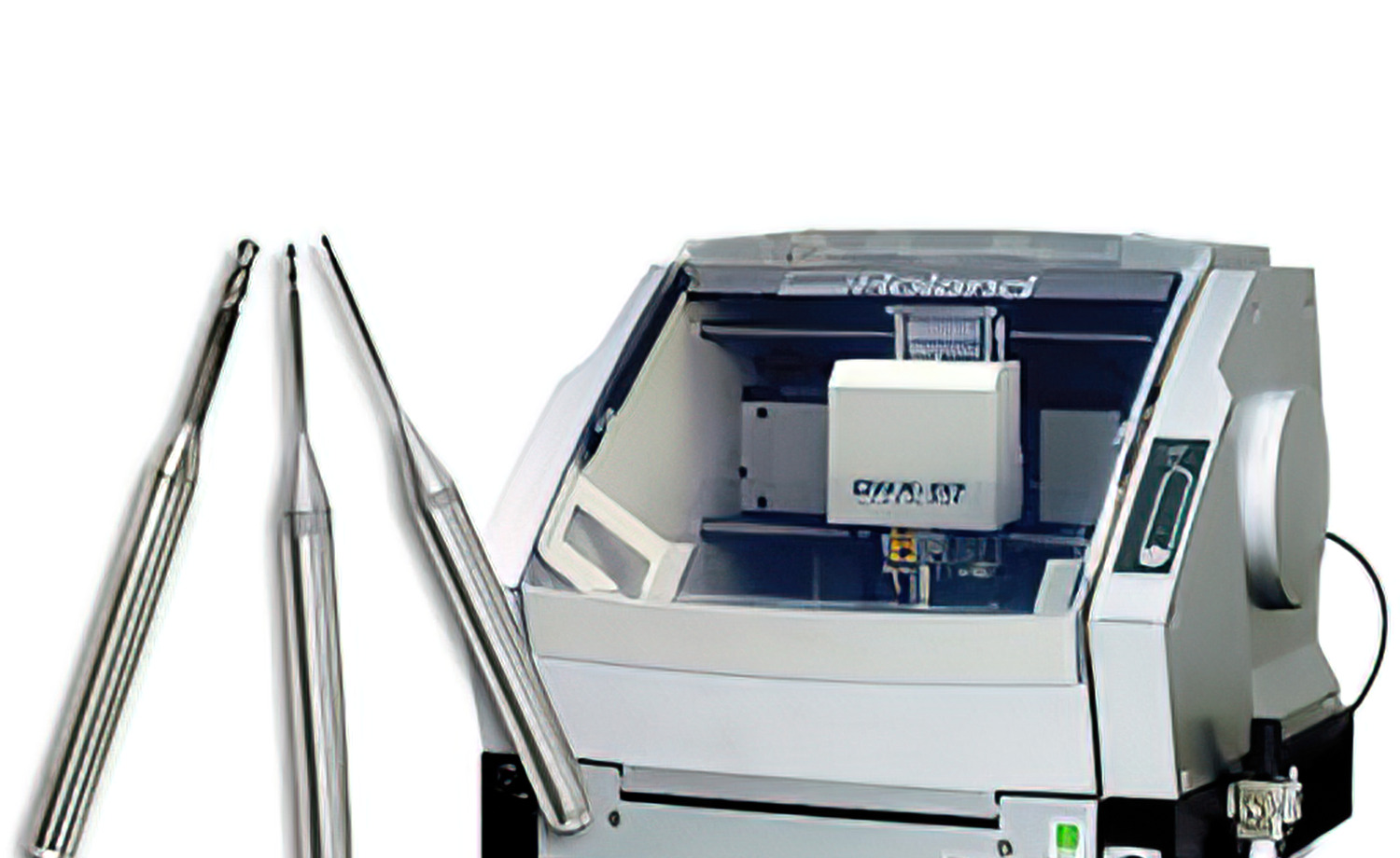
When researching dental laboratory tools, the term CAD/CAM comes up frequently. Whether you are a dental technician, lab owner, or practicing dentist, understanding CAD/CAM technology is essential for modern restorative workflows. This guide answers the most common questions about CAD/CAM in dentistry, covers the materials involved, and explains how milling burs fit into the process.
What Does CAD/CAM Mean?
CAD stands for Computer-Aided Design and CAM stands for Computer-Aided Manufacturing. Together, these two technologies form a digital workflow that takes a restoration from concept to finished product. CAD software creates a precise three-dimensional model on screen, while CAM software translates that model into toolpath instructions that guide a milling machine to carve the restoration from a solid block of material.
In dentistry, this workflow replaces many traditional hand-fabrication steps, offering higher consistency and faster turnaround times for crowns, bridges, inlays, onlays, and implant abutments.
Key Components of a CAD/CAM System
Every dental CAD/CAM setup includes three core components:
- Scanner — An intraoral or desktop optical scanner captures the tooth preparation and surrounding anatomy, generating a detailed 3D digital impression.
- Design software (CAD) — The technician or dentist uses the software to design the restoration, adjusting margins, occlusal contacts, and contours on screen.
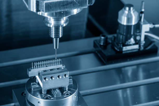
- Milling unit (CAM) — The milling machine receives the design file and uses rotating burs to cut the restoration from a material block, following programmed toolpaths with micron-level accuracy.
Advantages and Disadvantages of CAD/CAM
| Advantages | Disadvantages |
|---|---|
| Rapid, highly accurate production | High initial equipment cost |
| Consistent, repeatable results across units | Requires trained operators and ongoing software updates |
| Same-day single-visit restorations possible | Scheduled machine downtime for maintenance |
| Reduced material waste compared to casting | Material selection limited by block availability |
| Digital files can be stored and re-milled if needed | Learning curve for new users |
CAD vs. CAM: What Is the Difference?
While the two terms are often used together, they represent distinct stages. CAD is the design phase, where a digital model is created or modified on screen. CAM is the manufacturing phase, where that digital model is converted into physical instructions for a milling machine, 3D printer, or other fabrication device. In a dental lab, the CAD operator focuses on anatomy and fit, while the CAM process focuses on toolpath strategy, spindle speed, and bur selection.
How CAD/CAM Works in Dentistry Step by Step
- Digital impression — An optical scanner captures the prepared tooth and opposing arch, eliminating the need for traditional impression materials in chairside workflows.
- 3D modeling — The CAD software generates a virtual die and proposes a restoration shape based on the scanned data and a library of tooth morphologies.
- Design refinement — The operator adjusts margins, proximal contacts, occlusal anatomy, and material thickness to meet clinical requirements.
- Toolpath generation — The CAM software calculates the most efficient cutting strategy, selecting appropriate bur sizes and step-over distances.
- Milling — The milling unit carves the restoration from a material block using diamond-coated or carbide CAD/CAM milling burs, progressing from rough cuts to fine finishing passes.
- Post-processing — Depending on the material, the restoration may require sintering, staining, glazing, or polishing before cementation.
CAD/CAM Milling Burs: The Cutting Tools Behind Every Restoration
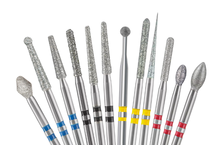
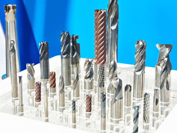
The milling bur is the direct interface between the machine and the material block. Bur geometry, coating, and diameter all affect surface finish, milling time, and tool life. Different machines require specific bur shanks and lengths. For example, milling burs for Imes-Icore 240 and 250 systems feature coatings optimized for zirconia, reducing heat buildup and extending bur longevity.
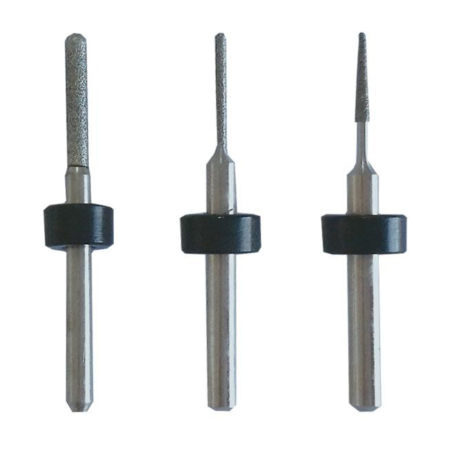
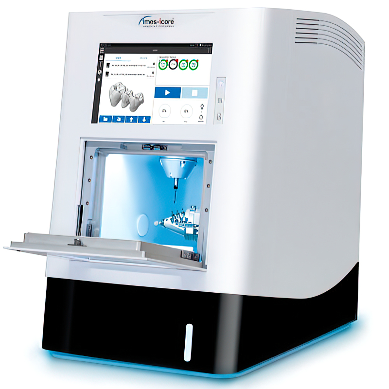
Choosing the correct milling bur matters. A worn or mismatched bur produces rough margins, increases milling time, and can cause material chipping. Replace burs according to the manufacturer's recommended cycle count, and always match the bur specification to the material being milled.
Common Materials Used in CAD/CAM Dentistry
Zirconia
Zirconia is a polycrystalline ceramic prized for its outstanding mechanical strength. It handles posterior load-bearing restorations well, including long-span bridges and implant-supported frameworks. CAD/CAM zirconia blocks are typically milled in a pre-sintered (green) state and then fired in a sintering furnace, where they shrink to final dimensions and reach full density. Modern multilayer zirconia blocks offer improved translucency, reducing the aesthetic gap compared to glass ceramics.
Lithium Disilicate
Lithium disilicate (e.g., IPS e.max CAD) combines good strength with excellent optical properties. It is a popular choice for anterior crowns and veneers where aesthetics are critical. The material is milled in a partially crystallized blue state and then crystallized in a furnace to reach its final shade and strength.
Resin-Based Materials
This category includes PMMA provisionals, composite resin blocks, and hybrid nanoceramic materials. PMMA is widely used for temporary restorations and surgical guides because it mills quickly and costs less per unit. Composite and nanoceramic blocks offer better aesthetics and wear resistance for semi-permanent restorations, and they are easy to adjust and polish chairside.
Glass Ceramics
Feldspathic and leucite-reinforced glass ceramics provide the highest level of translucency and natural aesthetics among millable materials. They are best suited for anterior veneers and inlays where visual appearance is the top priority and occlusal loads are moderate. These blocks are milled in their final crystalline state, which means no sintering step is required, but they are more brittle than zirconia and must be handled with care during milling and try-in.
Metal Alloys
Although less common in modern CAD/CAM workflows, certain milling systems can process cobalt-chromium and titanium blocks for implant frameworks and partial denture components. Milling metal requires specialized carbide or coated burs, higher spindle torque, and effective coolant delivery to manage the heat generated during cutting. The resulting frameworks offer excellent strength and biocompatibility.
Maintenance and Bur Replacement Schedules
Consistent output from a CAD/CAM milling unit depends on routine maintenance. Keep the spindle clean and lubricated according to the manufacturer's service intervals. Inspect collets for wear and replace them when they no longer grip the bur shank concentrically. Bur replacement schedules vary by material: zirconia burs typically last between 15 and 30 milling cycles, while burs used for softer materials such as PMMA or wax may last considerably longer. Track your bur usage with a simple log sheet or the built-in cycle counter on your milling unit. Running a worn bur past its service life increases the risk of marginal inaccuracies, surface roughness, and bur breakage inside the material block.
Who Uses CAD/CAM Technology?
CAD/CAM systems serve a broad range of dental professionals:
- Dental laboratories — High-volume labs use multi-axis milling machines to produce crowns, bridges, and implant components around the clock.
- Chairside dentists — In-office systems allow single-visit restorations, scanning, designing, and milling while the patient waits.
- Implantologists — Surgical guides, custom abutments, and screw-retained prostheses are all designed and milled through CAD/CAM workflows.
- Orthodontists — Clear aligner trays and digital models rely on CAD software for treatment planning.
Selecting the Right Burs for Your Milling Machine
Every milling machine brand has specific bur requirements in terms of shank diameter, overall length, and cutting geometry. Using non-compatible burs risks poor fit, premature wear, and potential damage to the spindle. When sourcing replacement burs, match the bur to your machine model and confirm the intended material. Burdental offers CAD/CAM milling burs compatible with major systems including Imes-Icore, Roland, Amann Girrbach, and others.
If you are new to the terminology used for rotary instruments, our guide on dental bur ISO numbers explains how bur coding systems work across manufacturers. For a broader overview of rotary cutting instruments, see our article on dental bur types.
Final Thoughts
CAD/CAM technology has fundamentally changed how dental restorations are designed and produced. From a single chairside crown to a full-arch implant framework, the combination of digital design precision and automated milling delivers predictable results with shorter production times. The quality of the final restoration depends not only on the software and the material but also on the milling burs doing the cutting. Investing in the right burs, and replacing them on schedule, is one of the simplest ways to maintain consistent output from any CAD/CAM system.